Wednesday, June 9, 2010
The BeagleTouch is an Open Source Hardware Module for the BeagleBoard. It’s inspired by concepts of modularity and rapid proto-typing, and continues Liquidware’s expansion into higher performance open source hardware.
Matt and I lined up one of almost every major modular gadget platform that he, Chris, Mike, and I have made over the past 2 years in one spot on the table. We called it “The evolution of Liquidware’s modular gadgets” and in tribute, found an old copy of Stephen Hawking’s A Brief History of Time.


First there was the Arduino and the TouchShield Stealth. This combination let anyone with an Atmel 168-powered Arduino Diecimila make small, handheld, portable, self-contained gadgets.

Then came the TouchShield Slide, for programmers with more demanding applications who wanted larger screen real estate, and a more accurate touchscreen to pair with the more powerful Arduino Duemilanove. The TouchShield Slide was featured on TV in NYC, used by celebrities, hacked by NASA, used for industrial design, and for rapid prototyping by the Department of Defense (no joke, they’re probably reading this right now and shaking their heads tsk tsk). The TouchShield Slide let the Arduino run Mario, and it has its own open source operating system, Pyxis, and a lightweight port of a small MacOS by Mark.

Then there was what Eric von Hippel would call “architectural innovation”, which is where the same modules are used over and over, but the architecture and the substrate changes and morphs as the modules are reconfigured into new setups.
This is the Arduino Gameboy Gamepack with an Arduino Duemilanove, Lithium Backpack, Doublewide Extendershield, Touchshield Slide, and Inputshield.

Here’s a picture of the Arduino Mega and the Mega Backpack with a TouchShield Slide:

Then there was the TripleWide Extender, which I used for the open source calculator project:

And now… hot on the tails of Apple’s announcement of the newest iPhone v4, Justin, Chris, Mike, Paul, and I present the new Open Source Hardware, modular BeagleTouch:
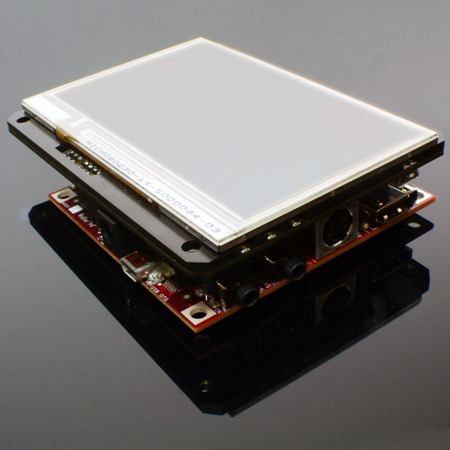
The BeagleTouch is a open source hardware modular screen, which snaps onto the BeagleBoard, and lets someone build and prototype handheld Linux gadgets.
Matt and I lined up one of almost every major modular gadget platform that he, Chris, Mike, and I have made over the past 2 years in one spot on the table. We called it “The evolution of Liquidware’s modular gadgets” and in tribute, found an old copy of Stephen Hawking’s A Brief History of Time.

First there was the Arduino and the TouchShield Stealth. This combination let anyone with an Atmel 168-powered Arduino Diecimila make small, handheld, portable, self-contained gadgets.

Then came the TouchShield Slide, for programmers with more demanding applications who wanted larger screen real estate, and a more accurate touchscreen to pair with the more powerful Arduino Duemilanove. The TouchShield Slide was featured on TV in NYC, used by celebrities, hacked by NASA, used for industrial design, and for rapid prototyping by the Department of Defense (no joke, they’re probably reading this right now and shaking their heads tsk tsk). The TouchShield Slide let the Arduino run Mario, and it has its own open source operating system, Pyxis, and a lightweight port of a small MacOS by Mark.

Then there was what Eric von Hippel would call “architectural innovation”, which is where the same modules are used over and over, but the architecture and the substrate changes and morphs as the modules are reconfigured into new setups.
This is the Arduino Gameboy Gamepack with an Arduino Duemilanove, Lithium Backpack, Doublewide Extendershield, Touchshield Slide, and Inputshield.

Here’s a picture of the Arduino Mega and the Mega Backpack with a TouchShield Slide:

Then there was the TripleWide Extender, which I used for the open source calculator project:

And now… hot on the tails of Apple’s announcement of the newest iPhone v4, Justin, Chris, Mike, Paul, and I present the new Open Source Hardware, modular BeagleTouch:

The BeagleTouch is a open source hardware modular screen, which snaps onto the BeagleBoard, and lets someone build and prototype handheld Linux gadgets.


Tuesday, June 8, 2010
DIY Gadgets with the BeagleBoard
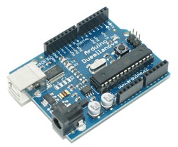
Matt and I have been building Arduino gadgets with shields for the past year or so. What I really like about the Arduino is that it has a standard pin header layout, which literally made DIY modular gadgets a snap:
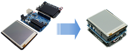 Looking at the BeagleBoard, however, it's not as obvious how to snap it all together.
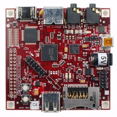 So I figured I would do a quick walkthrough of how to put together a DIY BeagleBoard gadget.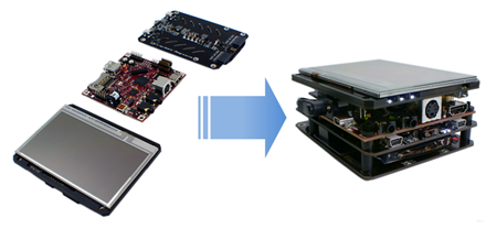
Step 1: Gather modules for the Beagle Gadget
One of the setups most folks used was a portable handheld display. It was a TouchShield Slide touchscreen on an Arduino Duemilanove, powered by a Lithium Backpack battery. Then it was just a matter of uploading different apps, menus, or pictures to the device.
To make something similar for the BeagleBoard, I grabbed my BeagleTouch display, BeagleBoard, and BeagleJuice battery pack, and my pre-formatted Liquidware BeagleBoard Linux boot SD card.
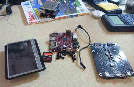
Step 2: Solder on pin headers to the BeagleBoard
The BeagleBoard has quite a few expansion headers - much like the Arduino. But unlike the Arduino, the standard BeagleBoard comes with the headers unpopulated, and most people just put on the headers that they'll need or think they'll be using.
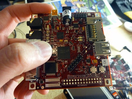
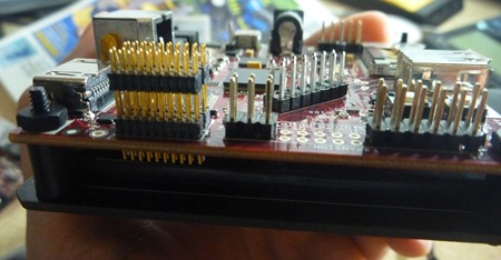
The BeagleTouch comes with a few extra headers that go onto the BeagleBoard, which I've soldered on like this:

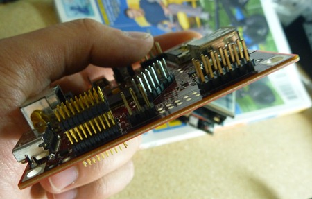
Step 3: Mount the BeagleBoard on the BeagleJuice battery
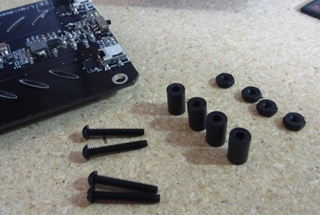
Since the BeagleJuice only needs to plug into the BeagleBoard's power jack, I'm securing it to the backside of the BeagleBoard. Like with the Arduino's Lithium Backpack, I'm using some plastic screws and standoffs that came with the BeagleJuice.
Step 4: Snap the BeagleTouch on the BeagleBoard and BeagleJuice
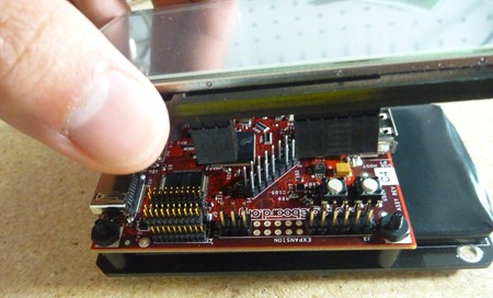
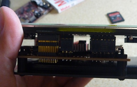
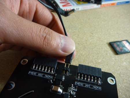
Now that I've added the expansion pin headers to the BeagleBoard, the BeagleTouch can snap right on. The back of the BeagleTouch also has female headers that connect to the BeagleBoard's serial pins, so I can talk to the entire setup over USB from my Linux laptop.
Step 5: Power up and boot!
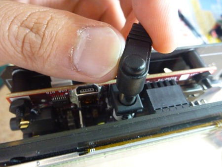
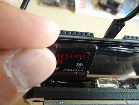
I've plugged in the BeagleJuice battery to the power jack, and I put the boot SD card into the BeagleBoard.
It's all ready to go, so now I just switch the power on, and Liquidware Beagle Linux boots up!
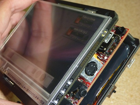
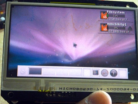
I've put everything I used in this tutorial over at the Liquidware shop, under Beagle Embedded Starter Kit. And here's a video demo of the Beagle gadget that Matt and I put together:

 Looking at the BeagleBoard, however, it's not as obvious how to snap it all together.
  So I figured I would do a quick walkthrough of how to put together a DIY BeagleBoard gadget.
Step 1: Gather modules for the Beagle Gadget
One of the setups most folks used was a portable handheld display. It was a TouchShield Slide touchscreen on an Arduino Duemilanove, powered by a Lithium Backpack battery. Then it was just a matter of uploading different apps, menus, or pictures to the device.
To make something similar for the BeagleBoard, I grabbed my BeagleTouch display, BeagleBoard, and BeagleJuice battery pack, and my pre-formatted Liquidware BeagleBoard Linux boot SD card.

Step 2: Solder on pin headers to the BeagleBoard
The BeagleBoard has quite a few expansion headers - much like the Arduino. But unlike the Arduino, the standard BeagleBoard comes with the headers unpopulated, and most people just put on the headers that they'll need or think they'll be using.

The BeagleTouch comes with a few extra headers that go onto the BeagleBoard, which I've soldered on like this:


Step 3: Mount the BeagleBoard on the BeagleJuice battery
Since the BeagleJuice only needs to plug into the BeagleBoard's power jack, I'm securing it to the backside of the BeagleBoard. Like with the Arduino's Lithium Backpack, I'm using some plastic screws and standoffs that came with the BeagleJuice.


Step 4: Snap the BeagleTouch on the BeagleBoard and BeagleJuice
Now that I've added the expansion pin headers to the BeagleBoard, the BeagleTouch can snap right on. The back of the BeagleTouch also has female headers that connect to the BeagleBoard's serial pins, so I can talk to the entire setup over USB from my Linux laptop.


Step 5: Power up and boot!
I've plugged in the BeagleJuice battery to the power jack, and I put the boot SD card into the BeagleBoard.


It's all ready to go, so now I just switch the power on, and Liquidware Beagle Linux boots up!


I've put everything I used in this tutorial over at the Liquidware shop, under Beagle Embedded Starter Kit. And here's a video demo of the Beagle gadget that Matt and I put together:
BeagleBoard Hello World
This is a BeagleBoard.
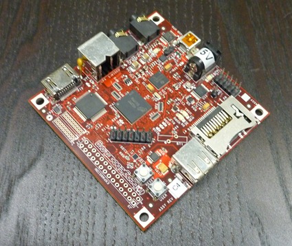
This is a BeagleBoard on drugs.
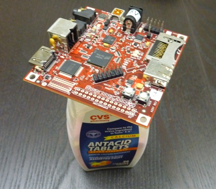 What a shame.
This is an SD card, specifically formatted by me and Chris using a ridiculously long, arduous process of trial and error before we finally figured out how to format it using a custom, homebrew version of Angstrom Linux.
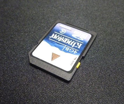 This is that same SD card, on drugs.
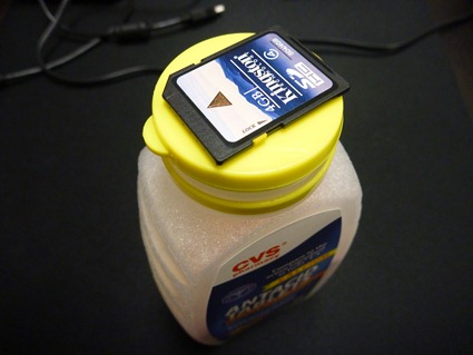 Yeah, now the joke is getting old.
The SD card is formatted (it’s available at the Liquidware shop pre-set up) with Liquidware BeagleBoard Linux, which is guaranteed to work (as opposed to the other flavors that are floating around that are guaranteed to take about 6 hours to get up and running). All the code is over at github:
http://github.com/liquidware/liquidware_beagleboard_linux
You can download it with the command:
git clone git://github.com/liquidware/liquidware_beagleboard_linux.git
cd liquidware_beagleboard_linux
git checkout liquidware
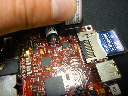
If you have an SD card already pre-formatted (e.g. because I gave you one at Maker Faire, or because it came with the BeagleBoard Starter Kit), plug it into the SD card slot on the BeagleBoard:
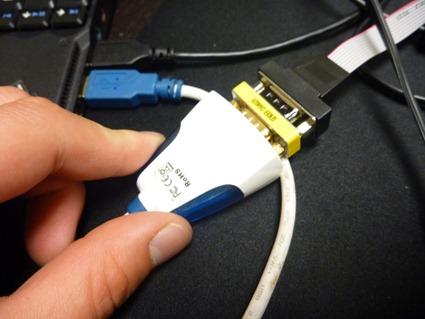
Then plug in the USB-to-serial cable crossover cable – this is a cable that specifically lets you plug in the BeagleBoard to the computer, and access it and program it over serial. It is deceiving, because it looks like a normal USB-to-serial cable setup, except that it needs a gender changer (there are so many jokes I could make right now but won’t) in order to swap Rx and Tx wires. I figured this out the hard way early on, when I had to solder up my own cable.
Then, plug the power cable into the BeagleBoard to power it on.

To see the BeagleBoard status and command line prompt over serial, type the following command into Linux:
screen /dev/ttyUSB0 115200
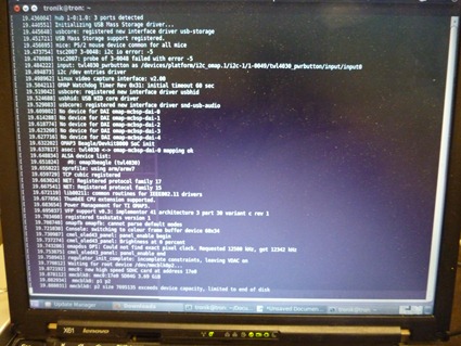
That will open a serial terminal monitor on Linux, and on Ubuntu (which is what I run), it is at the dev/ttyUSB0 port. The speed is 115200. If you’re on Windows, just open a terminal program and select the USB port you want, and set the speed to 115200. Voila. After a short while, you’ll see the BeagleBoard booting up, and then you’ll see a command line prompt:
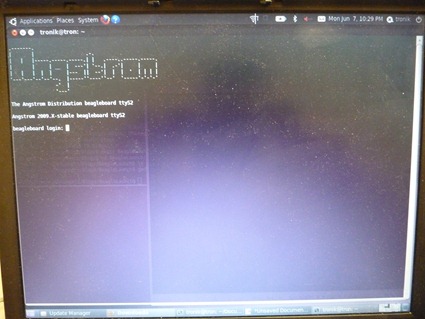
Angstrom Linux!
Ok, now you’re up and running!
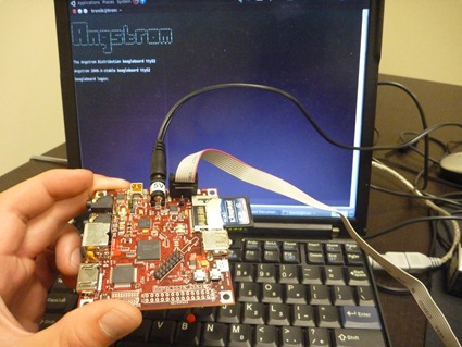

This is a BeagleBoard on drugs.
 What a shame.
This is an SD card, specifically formatted by me and Chris using a ridiculously long, arduous process of trial and error before we finally figured out how to format it using a custom, homebrew version of Angstrom Linux.
 This is that same SD card, on drugs.
 Yeah, now the joke is getting old.
The SD card is formatted (it’s available at the Liquidware shop pre-set up) with Liquidware BeagleBoard Linux, which is guaranteed to work (as opposed to the other flavors that are floating around that are guaranteed to take about 6 hours to get up and running). All the code is over at github:
http://github.com/liquidware/liquidware_beagleboard_linux
You can download it with the command:
git clone git://github.com/liquidware/liquidware_beagleboard_linux.git
cd liquidware_beagleboard_linux
git checkout liquidware
If you have an SD card already pre-formatted (e.g. because I gave you one at Maker Faire, or because it came with the BeagleBoard Starter Kit), plug it into the SD card slot on the BeagleBoard:

Then plug in the USB-to-serial cable crossover cable – this is a cable that specifically lets you plug in the BeagleBoard to the computer, and access it and program it over serial. It is deceiving, because it looks like a normal USB-to-serial cable setup, except that it needs a gender changer (there are so many jokes I could make right now but won’t) in order to swap Rx and Tx wires. I figured this out the hard way early on, when I had to solder up my own cable.

Then, plug the power cable into the BeagleBoard to power it on.
To see the BeagleBoard status and command line prompt over serial, type the following command into Linux:
screen /dev/ttyUSB0 115200

That will open a serial terminal monitor on Linux, and on Ubuntu (which is what I run), it is at the dev/ttyUSB0 port. The speed is 115200. If you’re on Windows, just open a terminal program and select the USB port you want, and set the speed to 115200. Voila. After a short while, you’ll see the BeagleBoard booting up, and then you’ll see a command line prompt:

Angstrom Linux!
Ok, now you’re up and running!

Monday, May 31, 2010
Up and running on the Humidity Sensor
Mike, Matt and I had a blast out at the Bay Area Maker Faire in San Mateo last week. It was great to put some faces to names, and talk to fellow hackers in person.
I had a couple folks asking about their Arduino greenhouse projects, and they mentioned it might be useful to have a humidity sensor to make sure the room didn’t get too dry.
So Paul and Chris built the Humidity Sensor, which is really a Humidity and Temperature Sensor, since it provides an integrated temperature reading as well. I’ve uploaded it over at the Liquidware and Modern Device shop pages.
 The Humidity (and Temperature) Sensor is a board that carries the SHT21 digital humidity and temperature sensor from Sensirion. It has 4 pins that can mount directly on the Arduino’s analog pins. Two of the four pins are Ground and +5V; the other two are clock and data pins making up the 2-wire serial interface.
It transmits data to the Arduino over an I2C protocol, and comes with built-in 5V tolerance to be powered directly from the analog pins. The Antipasto Arduino IDE has an integrated library that makes the humidity sensor plug-and-play.
Here’s a quick demo that Will and I put together, which maps out the relative humidity and temperature as a bargraph on the TouchShield Slide. Because the Slide doesn’t occupy any of the Arduino Duemilanove’s analog pins, I was able to mount both the Humidity Sensor and the Slide directly onto the Arduino.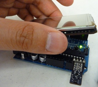


I took a video of the Humidity Sensor bargraphs in action:
And the code is below:
//Humidity sensor bar graphs - Arduino Code
#include
#include
#include
int h;
int t;LibHumidity humidity = LibHumidity(0);void setup() {
Sensor.begin(19200);
}void loop() {
h = (int)humidity.GetHumidity();
t = (int)humidity.GetTemperature();
Sensor.print("humidity", h);
Sensor.print("temp", t);
delay(5);
}________________________________________________//Humidity sensor bar graphs - TouchShield Code
#include
int newT;void setup() {
Sensor.begin(19200);
background(0);
line(0, 120, 320, 120);
text("RHumidity:", 0, 50);
text("Fahrenheit:", 0, 140);
}void loop() {
if (Sensor.available()) {
int h;
int t;
if (!strcmp(Sensor.getName(), "humidity")) {
h = Sensor.read();fill(0);
text(h, 230, 80);
delay(10);
fill(0);
rect(0, 70, 200, 30);
{
fill(0, 0, 255);
rect(0, 70, h*2, 30);
}
}if (!strcmp(Sensor.getName(), "temp")) {
t = Sensor.read();//convert celcius to fahrenheit
newT = (t*1.8 + 32);fill(0);
text(newT, 230, 170);
delay(10);
fill(0);
rect(0, 160, 200, 30);
{
fill(255, 0, 0);
rect(0, 160, newT*1.6, 30);
}
}
}
}


